V6calibra
C25XE Engine Coolant System
for vehicles with aircon
|
|
V6calibra |
|
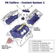
V6 Coolant System:
The V6 coolant system is controlled by a single thermostat and a series of coolant temp switches and relays. No part of the coolant system is controlled electronically by the Motronic ECU.
Total capacity = 7.5 litres (7.3 litres for auto gearbox versions)
Recommended UK mix = 60% distilled water + 40% Antifreeze
Expansion Tank Cap rated to 123 deg C and 1.5 bar pressure
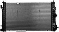
Main Radiator:
Cross Flow Type. 2300 cm2 core surface area.
Coolant temp switch mounted on side of radiator - S128
Auxiliary Radiator (aircon):
Cross Flow Type. xxxx cm2 core surface area. Mounted in front of the main radiator.
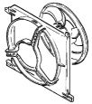
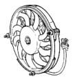
Main Fan Motor (M4):
Electric drive, 5 blades, 366 mm diameter. Max Air Flow = xxAuxiliary (booster) Fan Motor (aircon) (M11):
Electric drive, 10 blades, 2xxmm diameter. Max Air Flow = xx
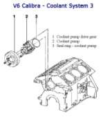
Main Water Pump (mechanical - belt driven):
The main water pump is mechanical in operation and is driven by the auxiliary ribbed v-belt. Water pump output is proportional to engine rpm. Only operates when the engine is running. Pump bearings do fail with time. Plan on replacing every 80,000 miles (every other cambelt change).
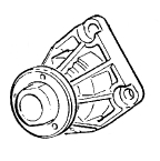
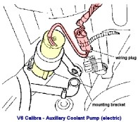
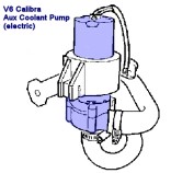
Auxiliary (secondary) Water Pump (M57):
Small electric drive coolant water pump. Mounted at the side and base of the main radiator. Required to drive coolant around the system after engine has been turned off. This is one of the noises you hear start up after then engine has been turned off when warm.
Interior cabin heat exchanger / Heater Matrix :
The heater matrix is used to provide heat to the interior cabin ventilation blower. The engine coolant system is routed through the engine bay bulkhead and into an additional radiator like component (heater matrix) which is installed inside the vehicle.The heater matrix is prone to leaking with age. If you suffer a slow coolant loss then check for signs of the matrix leaking:
Wet front footwell carpets
Some report hearing a sloshing water sound from the plastic matrix retaining tray.undo four bolts and remove
cover by sliding backwardsundo the restraining straps and
remove the heater matrix core
Replacing the matrix involves stripping out the lower interior dash console and side panels to gain access to the matrix plastic hosing cover. The coolant system connections are accessed from inside the engine bay.
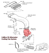
Alternator Cooling Fan Motor (M23):
Small electric turbine fan. Sucks cool air in through the large flat black plastic duct to the right of the engine. It blows it through a duct pipe down to the alternator cooling shroud. The cool air is flowed around the alternator body helping to keep it cool. This 'feature' was added to help minimise premature alternator failure due to the high temperature environment of the V6 engine bay. It helps, but alternators are a consumable item on the V6.
This is another one of the noises you hear after then engine has been turned off when warm. It uses the run on relay to cool the alternator down after stopping.
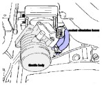
coolant circulation hoses shown in blueThrottle Body Coolant Circulation:
Coolant is circulated through the base of the throttle body. Coolant is fed through the small diameter topmost rubber hose from the coolant bridge and is returned using the same diameter hose back into the top of the coolant header tank. This is designed to minimise residual heat build up in the throttle body - it does not cool the intake air.
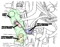
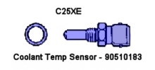
Coolant Temperature Sensors:
The V6 has two screw-in CTS's. However, they have nothing to do with controlling the V6 cooling system. They are used to monitor the actual coolant temperature in the coolant bridge and they report back to:
1: the dash coolant temp gauge
2: the main Motronic ECU
and 3: is the second coolant temp switch (S29)
The main one to watch out for is the ECU CTS (with a blue coloured connector). The ECU needs to know the coolant temp to help it to adjust for engine running conditions (cold start, etc).. The dash gauge CTS has a single black wire connector.
ECU CTS Sensor Test
Disconnect harness socket and connect voltmeter across pins in the sensor plug.
Measure the resistance across the pins, this varies with the temperature:
17.8 deg C = 2530 ohms
22.0 deg C = 2250 ohms
25.0 deg C = 1680 ohms
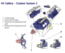
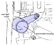
V6 Thermostat (bypass regulator type)
Mounted inside tubular housing.
Starts to open at 92 deg C
Fully open at 107 deg C
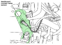
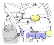
Bleeding air from the coolant systemAir in the coolant system should be bled out at the highest point on the cooling system. The recommended bleed point is the dash-board coolant temperature sensor sender. This is the single black wire connector sensor screwed in to the coolant bridge. Air locks in the coolant system leads to poor cooling of the engine and inferior operation of the interior hot air heater and demister.
When checking or topping up the coolant system always keep an eye out for a brown mayonnaise like substance. If this is found floating around in the coolant expansion tank or inside the radiator hoses, then it is an indicator that either your head gaskets have gone and/or the oil cooler has rusted through and is leaking oil out into the cooling system. The longer you leave this problem the worse the cooling system contamination will get; you must take prompt action to repair. If contamination of the coolant system has occurred you will need to flush out with a flushing agent before replacing with new coolant.
bleed point location in coolant bridge
coolant expansion tank cold level markTo bleed the air out of the system:
With the engine cold, check the coolant level in the expansion tank. It should be on the cold (kalt) marker
Top up as required with distilled/de-ionized water + anti freeze mix (60% water to 40% antifreeze is OK for UK)
Start engine and run up to operating temperature so thermostat starts to open - 92 degrees C
With engine running carefully remove the dash-board temperature sender to allow excess coolant to flow out
Squeeze and pump the radiator hoses to ensure there are no trapped air bubbles
Turn off the engine, replace the coolant temp sender and allow to engine to cool
Check the level in the expansion tank and top up as required.
Repeat this process until all the air is bled from the cooling system
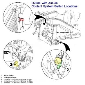
Coolant System - Switches and Relays
click image for larger view
Coolant Switch Locations
Coolant Temp Switch (S29):
Located in the coolant bridge. It is the one below the blue CTS plug. The wiring harness connector is a squashed oval two pin plug.
Main fan + Booster Fan On at 100 deg C via relay K26
Main fan + Booster Fan Off at 95 deg C via relay K26Also triggers operation of alternator cooling fan motor M23
Coolant Temp Switch (S128) (aircon or non-aircon versions available) :
Located in the upper half of the cooling system. On the radiator upper edge. The wiring harness connector is a round three pin plug.
At 105 deg C
Auxiliary (booster) fan on - stage1 via relay K26
Main fan on - stage1 via relay K26
At 120 deg C
aircon clutch disengaged (a/c override)
aircon clutch re-engage again after cooling to 105 deg C
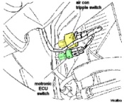
Triple Switch (aircon only) (S20): S20.1 - aircon low pressure safety switch : triggered when either ambient temp is too low to run a/c or if there is low (or no) refrigerant in the a/c system. Activates at 1.8 bar refrigerant pressure and disengages a/c compressor clutch. The power to the compressor is also switched off to prevent damage if no refrigerant. The switch deactivates when the pressure reaches 2.5 bar.
S20.2 - aircon high pressure safety switch : Activates at 30 bar refrigerant pressure and disengages a/c compressor clutch. Deactivates when the pressure drops to 20 bar and compressor re-engaged.
S20.3 - booster fan stage2 switch : Activates at 19 bar refrigerant pressure and switches main fan and booster fan to stage2 operation. They are both assumed to be already running at stage1 as turning on the a/c also activates both main and booster fans in stage1 mode. When the pressure falls to 14 bar both fans are switched back to stage1 operation. Uses relay K67Motronic Switch (aircon) (S109):
This is what causes the momentary dip in the engine rpm when you switch a/c on.
Monitors a/c high pressure circuit. Activates when the refrigerant pressure exceeds 11 bar. Engine RPM is adjusted by Motronic to compensate for a/c compressor increased engine loading. Deactivates when the pressure falls below 9 bar. The Motronic no longer compensates engine idle speed.
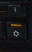
A/C Dash Switch (aircon only) (S101):
The aircon dash switch turns the aircon on and off. When you turn the a/c on both the main and booster fans are switch on in stage1 mode using relay K26.
The orange light in the a/c switch is a separate a/c operation indicator. It is routed via the triple switch low pressure monitor circuit and only illuminates orange if low pressure conditions are not detected (i.e. refrigerant pressure > 1.8 bar)
Relays:
K6 : Aircon relay - triggered by dash aircon switch (S101)
K22 : Auxiliary Electric Coolant Pump relay M57
K26 : 6v power to Main Fan M4 and Booster Fan M11 - STAGE1 mode operation
also power to electric coolant pump M57 and alternator cooling fan M23
K27 : Fan Motor relay (M4 & M11)
K51 : Fan Motor relay (M4 & M11)
K52 : Fan Motor relay (M4 & M11)
K67 : +6v power switched in parallel with K26 and powers M4 and M11 up to STAGE2 mode operation
K87 : Fan Motor relay (M4 & M11)
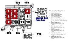
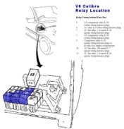
Where are these relays ?
relay locations - engine bay fuse box
relay locations -
behind interior fuse box
Other Related Components:
M10 : Interior cabin fan/blower motor
Y1 : Aircon compressor clutch
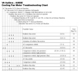
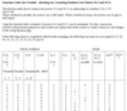
V6 Fan Motor Troubleshooting Charts:
Fan Fault Table
Fan Test Table