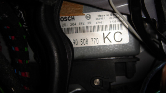
V6 Calibra C25XE - Bosch
Motronic 2.8
Snapshot Mode - format of
ECU output
The ECU can be instructed to go into Snapshot
mode. In this mode it provides a constantly updating list of engine and
ECU performance parameters. This list is sent as one single long data frame
(?).
The list below represents the parameters which are passed
and their position and format within the broadcast data frame. Where
applicable any modifiers required to obtain actual engineering units are
listed.
SNAPSHOT INITIATION AND GENERAL FORMAT NOTES:
## incomplete
This is what we have so far based on Tech 1a operation :
| Data Parameter
Identifier |
Description & Raw
Signal Modifier |
Data Frame
Byte Pos. |
|
BATTERY VOLTAGE |
Voltage
supplied to the Motronic ECU (volts DC) |
|
| TPS
SIGNAL |
Throttle valve
Position Sensor signal (%) |
|
| SIM.
IDLE POS. SW |
Idle position
on actual TPS sensor signal range (volts dc ?) |
|
| SIM.
FULL POS. SW |
Full throttle
position on actual TPS sensor signal range (volts dc ?) |
|
| INTAKE
AIR TEMP. |
Air Intake
Temperature sensor value (deg C) |
|
|
COOLANT TEMP. |
Coolant
Temperature Sensor value (ECU CTS) (deg C) |
|
| MASS
AIR FLOW S. |
Signal from
Mass Air Flow Meter |
|
| ENGINE
LOAD SIG. |
Inferred engine
load in milliseconds calculated from the Mass AFM value |
|
| KNOCK
SIGNAL |
Signal from
knock sensors (only when knock is being detected) |
|
|
VARIANT CODING |
Setting of
variant coding plug (Side A or Side B) |
|
| HALL
SENSOR |
Camshaft
Position Sensor value |
|
|
VEHICLE SPEED |
Processed
signal output from odometer frequency sensor |
|
|
VEHICLE SP.PULSE |
Raw signal from
odometer frequency sensor |
|
| A/C
INFORMAT. SW |
Air
Conditioning Switch state (switch on the dash) |
|
| A/C
COMPESS. SW |
Air
Conditioning Compressor status |
|
|
PARK/NEUTRAL SW. |
Auto only -
Position of Auto Gear selector |
|
| TORQUE
CONTROL |
Auto only -
Shift signal from Auto gearbox ECU |
|
| FULL
LOAD INHIB. |
Traction
Control has been activated signal from TC ECU |
|
|
IGN./INJ. CUTOFF |
Ignition /
Injection cut off signal received from TC ECU |
|
| IGN.
COIL CYL1+4 |
Ignition Coil
is activating for cylinders 1 and 4 |
|
| IGN.
COIL CYL2+5 |
Ignition Coil
is activating for cylinders 2 and 5 |
|
| IGN.
COIL CYL3+6 |
Ignition Coil
is activating for cylinders 3 and 6 |
|
| ENGINE
LOAD SIG. |
Processed
engine load signal based on actual TPS value |
|
| TPS
LOAD SIGNAL |
Processed TPS
value |
|
| FUEL
PUMP RELAY |
Fuel Pump Relay |
|
| A/C
CUTOFF RELAY |
A/C Compressor
Cutoff Relay activated |
|
| FUEL
TANK VENT. |
Fuel Tank Vent
Valve (Carbon Canister Vent Valve) activated |
|
| ENGINE
SP. PULSE |
Raw Ignition
Pulse (RPM) from Crankshaft sensor |
|
|
DESIRED IDLE |
Normal desired
engine idle speed (from variant coding plug and ECU MAPs) in RPM |
|
| ENGINE
SPEED |
Actual observed
engine RPM when in idle mode |
|
|
DESIRED AIR IDLE |
Desired
incoming air mass for target idle rpm (from ECU MAPS) |
|
| ACTUAL
AIR IDLE |
Actual incoming
air mass when engine in idle mode |
|
| IAC
INTEGRATOR |
Integrator
value of Idle Speed Control Valve adjustment |
|
| IAC
ADAPT. SLOPE |
Deviation of
idle speed adjuster pulse ratio from value calculated by the ECU
|
|
| IAC
BLOCK LEARN |
'Learned' value
of ISCV position |
|
| O2
SENSOR LOOP |
Indicates
whether ECU is operating in Open or Closed loop oxygen senor mode. |
|
| O2
SENSOR |
Oxygen sensor
value (in mV) |
|
| O2
INTEGRATOR |
Integrator
value of mixture correction factor |
|
| O2 BLM
IDLE THR. |
Learned mixture
characteristic MAP value when operating in idle speed mode |
|
| O2 BLM
PART THR. |
Learned mixture
characteristic MAP value when in partial engine load range |
|
| SPARK
ADVANCE |
Calculated
Ignition firing angle (before top dead centre mark) currently being used
by the ECU
(value is between -30 and + 30 degrees BTDC) |
|
| KNOCK
RETARD |
Ignition timing
adjustment to be applied to calculated Spark Advance value. This value
comes from internal ECU Knock Function segment when knock is actively
being detected through knock sensors. |
|
|
INJECTION PULSE |
Calculated
Injection pulse period (pulse width) in milliseconds |
|
| CHECK
LIGHT |
Engine
Management Fault light tripped (ON/OFF) |
|
| DIAG.
REQUEST |
Request
received to go into diagnostic blink mode - snapshot suspend |
|
|
INJECTOR CUTOFF |
Injector cutoff
triggered by internal ECU functions (O2 sensor feedback) |
|
|
CONTROLLED IAC |
Control Idle
Air Speed Valve adjustment value |
|
PRINCIPLES BEHIND ECU OPERATION
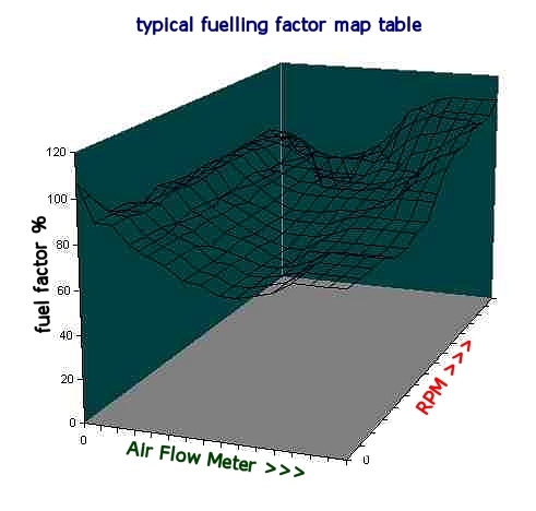
FUEL MIXTURE GOALS:
It is desired that the correct amount
of fuel to match the incoming air be sprayed into the engine. Generally there
shouldn't be any extra air, or any extra fuel. Under light loads, the system
will try to go slightly lean (extra air). Under heavy loads, the system will
try to go slightly rich (extra fuel). The incoming air is measured by the mass
air flow meter (hot film type); quantity of real air flow mass is achieved by
adjusting for air intake temperature. Fuel quantity is estimated from an ECU
look up table based on the specifications of the stock Bosch injectors.
When the ECU is in 'closed loop mode', the duration of the injector pulse
dictates how much fuel is delivered and this is indirectly adjusted using
feedback from the lambda sensor in the exhaust (rich/lean air/fuel ratio in
exhaust gasses).
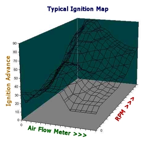
SPARK TIMING GOALS:
The sooner the spark is fired before
the piston reaches the top (spark advance), the higher the resulting
combustion temperature and pressure will be (a similar effect to increasing
compression ratio). This will also allow a slightly greater time for the
pressure to be applied to the piston. All of this results in more power and
better fuel efficiency. CO and HC emissions are reduced because combustion is
more complete. If the timing is advanced too much, however, an uncontrolled
explosion will result (engine knock). This can cause engine damage (piston
melting) and will increase NOx emissions because the extremely high
temperatures will start to oxidize the normally unreactive nitrogen in the
air. It is very desirable from performance, economy, and emissions standpoints
that spark timing be advanced to just below the point where knock occurs. To
this end the Motronic makes use of two knock sensors; One for each bank of
cylinders. These sensors are used to detect the initial signs (precursors) at
the onset of engine knock. The feedback from these sensors is used to help the
ECU dynamically advance the ignition timing to optimum. They are basically
small microphones bolted to the engine block which react to vibrations of a
certain frequency. They scan every 100 milliseconds.
CONTROL MAPS AND ADAPTIVE
TUNING:
When trying to determine the spark timing and fuel
requirements, the Motronic system reads information from the operating sensors and then goes to some big look-up tables (or
Control MAPS) that indicate the best guess for spark and fuel at that moment.
The feedback sensors are then used to tweak the spark and fuel values towards
an optimum. If a big 'tweak' was needed, then the firmware will change the
value in the look-up table with the hope that it will be closer the next time
that data point is used (Adaptive Tuning). All of this process is continuous,
and it cycles and repeats at a high frequency. This adaptive tuning feature
means that the Motronic is capable of 'learning' the specific settings for
your engine. This also means that the ECU is able to re-optimise engine
tuning after minor modifications have been made (e.g. enlarged throttle body).
However, this adaptive feature does have limits.
The Motronic system contains a 'base
map' that is copied over to the active control map when the system loses power
or is otherwise re-initialized. This is useful if there was a malfunctioning
component or something else that caused the active map to get messed up. You
can also force the adaptive map to reset to default after modifying engine
components in order to learn a new set of adaptive parameters based on
original values (rather than your engines old adaptive control maps).
How long does it take for adaptation to
fully readjust the map after a change? Hard to say.
Some points on the map will be updated
fairly quickly. Others might take a long time.
Remember that the map is fairly big.
For a data point to be updated, it has to be used. To go through the whole map
would require the engine to go through all the combinations of temperatures,
loads, warm-up cycles, etc.
REPROGRAMMING THE SYSTEM:
Motronic 2.8 system stores the code on
an EPROM chip. This needs to be physically replaced to update the ECU code and
base reference maps. In order to do this yourself you would be best advised to
download the original contents of the ECU EPROM (EPROM dump)........
understand it....... extract the control maps ......... make modifications and
recode ...... then write it out to a new EPROM chip to replace the original.
This kind of activity requires specialist equipment and is beyond the scope of
most DIY'ers.
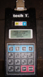
DECODING THE SYSTEM:
To communicate with the Motronic ECU a dealer uses a
handheld device known as a 'Tech 1'. This plugs in to the vehicles diagnostic
socket and communicates over the vehicles ALDL bus. Serial asynchronous 5 volt
DC pulses are used to communicate with (and control) the Motronic ECU. The
Tech 1 is capable of performing the following actions and functions:
|
 |
- Read all diagnostic fault codes in text form (main
ECU, ABS, TC, ATWS, Alarm, Immobiliser, airbag, Auto gbox)
- Reset/Clear fault codes
- Snapshot data mode - continuously outputs all sensor
values and derived ECU parameters
- Reset airbag ECU and recode immobiliser transponder
key
- initiate actuator tests - ABS, Traction Control, Fuel
Tank Vent Valve, etc.
- dump a copy of the contents of all control map tables
|
The are two versions of the
Tech1 which were used by Vauxhall. The early ones are just a Tech1 the newer
ones are know as the Tech1a. You can easily tell the difference. Tech1 has a
15way D PLUG and the Tech1a has a 26way HD (3 line) D SOCKET. The Tech1a also
has a power socket and a RJ45 socket on the side for connecting to the RS232
port of a PC (the Tech1 requires an additional cartridge to add this
functionality)
They are very much
functionally identical for most tasks. The main difference is you cannot
program a MSC with a Tech1 unless you have the optional plug in communications
module (with RJ45 socket). You also have to power the unit from the car (you
can't power it on the bench!).
You need
the Tech1 cartridge marked "Vauxhall/Opel 1987 - 1993" or later
MSC version to communicate with the C25XE Motronic v2.8
ECU.
Tech2
superseded the Tech1/1a and is also capable of communicating with the Motronic
2.8
Both Tech1 and Tech2 are prohibitively expensive. When new
this kit costs a dealer £2,500 - £5000. The now defunct Tech1/1a readers can
occasionally be picked up for £200-£500. It is useless without the correct
application cartridge and cable however.
There are some aftermarket readers like 'ScanTool' which
can also provide some limited functionality. These are also pretty expensive
and aimed at a wide selection of vehicles and manufacturers.
It is reasonable to expect that a PC based solution would
also be capable of communicating and controlling the ECU. The standard serial
port on a PC or laptop can be connected to the ALDL bus using a custom cable
and hardware interface. The interface is required to convert standard PC
serial com port I/O to a 5 volt bi-directional half duplex signal.
|
Andy Whittaker's ALDL 8192
Interface |
|
|
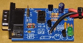
This ALDL interface can be used to talk to
the Motronic 2.8 ECU but this isn't much good unless you know the command
and data frame formats
|
The data is in TTL (i.e. 5V), bi-directional
(half-duplex) format and runs at 8192bps.
8 data bits, no parity bit, and 1 stop bit
Commands to the ECU are organised into groups of bytes called command
frames. In response to certain command frames the ECU sends data
frames. Analysing these data frames on a PC requires you to first
know the data frame format. For the Motronic 2.8 this information is not
publicly available.
|
EFIlive v4
can be used to send ECU commands and receive results (http://www.efilive.com/scan_4.html).
They offer a freeware version of their professional ECU tool in the downloads
section.
Also try
http://www.andywhittaker.com/ecu/download.htm for his FreeScan tool
Very little is known about the proprietary command and data frame structures
used in the Bosch Motronic 2.8. Without this knowledge it may be possible to
initiate communications with the ECU but impossible to control or make any
sense of the returned data.
At this time there is no information available on the Motronic 2.8 frame
structure and protocol.
The only way forward is to obtain this proprietary information from
Opel/Vauxhall OR to reverse engineer the serial data comms by listening in on
the Tech1 when it communicates with the ECU.
If anyone is able to provide more information on this subject please share it
with the community and
email me
SOME BACKGROUND AND RELATED INFORMATION:
8192 Baud Asynchronous Communications
from :
http://www.geocities.com/MotorCity/Shop/9938/diagnostics/baud8192.html
General Description.
The 8192 GM data format is
asynchronous serial data the same as your PC is capable of processing, The
8192 baud rate is non-standard, but you can set the PC to a close enough so
that the PC will accommodate the error.
The GM system is a master/slave
system. Thus feature allows the vehicle to have multiple computers on line and
avoids collisions between talker. E.G. main ECU, Traction Control ECU
The user must initiate a short message
to inform the receiving device that information is being requested. This
message must conform to a specific format, describing the requested
information as a block.
To Establish diagnostic
communications between a P6 or P66 ECM or PCM and an outside computer do the
following:
- Mode 0 request, this clears any
other communications such as the body computer, (dash board) , ABS brakes
Etc.
- Mode 1 request, This is a
request for the diagnostic data stream, generally 60+ bytes of parametric
data.
MESSAGE ID = $F4
MESSAGE LENGTH = $56
MODE = $00
SUM CHECK |
MESSAGE ID = $F4
MESSAGE LENGTH = $56
MODE = $00
SUM CHECK |
MESSAGE ID = $F4
MESSAGE LENGTH = $57
MODE = $01
MESSAGE = $00
SUM CHECK
or
F45701B3 |
Note:
1. The sum check is the complement
of the message. When the incoming message is added it
will always have a LSB of $FF
2. The message length is always $56 + the actual count of data bytes, in
this case 1 byte
- The ECM/PCM Will Reply:
MESSAGE ID = $F4
MESSAGE LENGTH = $95
MODE = $01
data byte 1
x
x
data byte 63
SUM CHECK |
- To get another update the user
must send another Mode 1 Request.
Possible data Reading Schemes:
The commercial scan tools generally
use a 6800 series Motorola processor to decode and display the data. These
commercial systems also convert the output to a standard serial data rate
that is readable by a PC. The problem with all of this is it becomes a "kluge"
of cables to set all of this up and the data format may not be what you want.
A more attractive method would be
to eliminate the real time display part and have a small Microprocessor, (PIC
Chip) translate the data and store it in a flash memory chip. I have found it
very difficult to read and interpret data while driving, particularly if I'm
using the data to do a tune up. I prefer looking at the results on my desk top
and in some cases graphing them in order to calculate new values.
Other Communications
Features:
The serial
communications has several modes Typically:
- Mode 2, Dump 60
bytes of memory starting with a user defined address.
- Mode 3, dump of
any 8 user defined address's
- Mode 4,
Controller mode, User may change AFR, Spark, TCC etc.
- Mode 10, Clear
diagnostic errors, (clear codes)
An example of Mode 2:
- To Execute a
Mode 2, Transmit the following message:
MESSAGE ID
= $F4
MESSAGE LENGTH = $58
MODE = $02
Address MSB
Address LSB
CHECKSUM |
MESSAGE ID = $F4
MESSAGE LENGTH = $96
MODE = $02
data 1
x
x
data 64
SUM CHECK |
An example of Mode 3,
- To Execute a
Mode 3, Transmit the following message:
MESSAGE ID = $F4
MESSAGE LENGTH = $65
MODE = $03
Address 1 MSB
Address 1 LSB
x
x
Address 8, MSB
Address 8, LSB
CHECKSUM |
MESSAGE ID = $F4
MESSAGE LENGTH = $63
MODE = $03
data 1
x
x
data 8
SUM CHECK |
An example of Mode 10,
"Clear Error Mode":
- To Execute a
Mode 10, Transmit the following message:
MESSAGE ID
= $F4
MESSAGE LENGTH = $56
MODE = $0A
CHECKSUM |
MESSAGE ID = $F4
MESSAGE LENGTH = $56
MODE = $0A
SUM CHECK |
LOTUS ELAN ECU INFO
(from http://www.syntaxis-technology.co.uk/lotus/aldl.html)
The format is standard NRZ serial data at 8192 baud, 8N1 format. You can
use 9600 baud on a PC - the framing errors are not excessive.
When the ALDL has a 10K resistor between Diag Request and ground, it goes into
diagnostic mode [there are other modes, but they're not important]. The ECU
will then sit and wait for you to talk to it. You send a framed command, which
the ECU echos, and retrieve a block of data, containing current information
about the engine status. Note that there's no flow control on the ALDL line,
so once you've sent your command, read like hell to get the returned
data.
The data returned by the ECU in response is framed in a similar manner to your
command. You can also enquire of trouble codes and clear them.
The frame format is:
| Length |
Meaning |
| 1 byte |
Device ID |
| 1 byte |
VLI (86+N where there are N data bytes) |
| 1 byte |
message ID [command basically] |
| N |
data bytes |
| 1 byte |
checksum (2's complement of the preceding bytes) |
The Elan ECU Device ID is F4.
I'm documenting the possible message ID's at the moment, but they appear to be
00,01,02,03 and 06.
Currently, 01 looks like the interesting one - it dumps a large block of data
back.
This is what is currently known about the Elan ECU data stream returned
from a message of type 01.
| Byte offset |
Meaning |
Conversion |
| 9 |
Temperature °C |
N*0.75 - 40 |
| 12 |
Timing |
1 ° per bit |
| 13 |
Timing (again) |
ditto, but 0° reference |
| 14 |
RPM |
25RPM per bit |
| 34,35 |
Engine run time (seconds) |
34=MSB, 25=LSB |
LINKS
http://www.mskar.org/atlantis.php?page=Motronic%20Editor
http://www.efilive.com
http://www.andywhittaker.com and
http://sourceforge.net/projects/freescan/
http://www.diy-efi.org/gmecm/